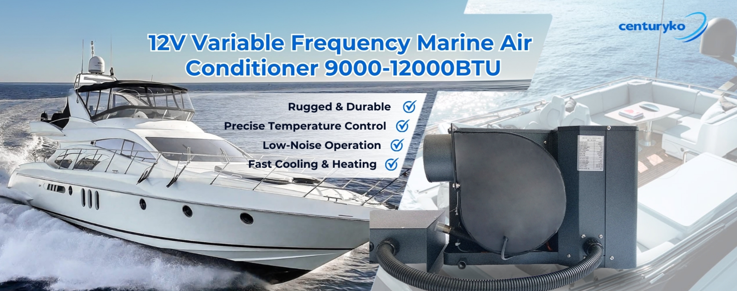
Practical overview for boat owners and installers
When choosing equipment for a vessel, the difference between a compact tube bundle and a wide shell path can change comfort, service intervals, and energy draw. This guide focuses on what you actually need to know about shell-and-tube geometry in relation to a dc marine air conditioner, and how those choices affect real-world operation of marine air conditioning units. I’ll use plain language, pointing at heat transfer, refrigerant flow, and seawater cooling considerations so you can make decisions that hold up at sea. The terms marine air conditioning units and dc marine air conditioner will appear naturally as we discuss design trade-offs.
Key structural differences and what they mean
Shell-and-tube condensers vary by tube diameter, tube count, and shell baffle arrangement. A tight tube bundle (many small-diameter tubes) increases surface area for a given shell size, raising heat transfer coefficient for the refrigerant side. Larger-diameter tubes reduce fouling sensitivity but lower refrigerant-side convection. Baffles inside the shell force seawater through a controlled path, improving cooling but also increasing the risk of sediment trapping on long coastal passages where water is turbid.
User-centric importance: durability, efficiency, and serviceability
For owners of small yachts or commercial craft, the priority is rarely peak lab efficiency—it’s uptime and straightforward maintenance. A shell-and-tube condenser optimized for easier access to the tube bundle reduces haul-out time and lowers labor cost. Conversely, performance-minded skippers want finer tubes with a denser bundle for higher BTU/hr per unit mass; that typically pairs with a DC compressor capable of variable-speed modulation to match load. Choose the configuration that lines up with your operating profile—short charters near marinas favor easy-clean designs, long ocean passages need corrosion-resistant materials and redundancy.
Installation pitfalls and common mistakes
Many retrofit jobs go sideways because installers treat condenser selection like a one-size swap. Common missteps include undersizing sea strainers, failing to account for additional pressure drop from tighter baffle spacing, and neglecting galvanic isolation between condenser shell materials and hull fittings. Also, skip the temptation to prioritize lowest cost tubing over alloy selection—seawater-cooled condensers exposed to warm, saline water (think Panama Canal transits or heavy Mediterranean use) will corrode faster unless metallurgy is appropriate.
Operational teardown: how components interact
Think of the condenser, compressor, and evaporator as a single circuit. The condenser’s tube bundle determines refrigerant condensation rate; the compressor’s capacity and control logic determine flow and pressure; the evaporator sets the cabin load response. If a condenser restricts flow too much, the compressor runs hotter and cycles more—shortening component life. Conversely, oversized condenser area with poor seawater velocity yields marginal gains because heat transfer is limited by the water-side film coefficient, not the refrigerant-side area.
Quick retrofit checklist
Follow these practical steps before swapping a unit:
– Confirm seawater temperature and expected turbidity for your operating regions (tropical vs. temperate).
– Match condenser pressure drop to compressor performance curve; ask for pump head specs and compressor map.
– Specify alloys and coatings for tube bundle explicitly—braze versus welded, copper-nickel versus titanium—based on salt load.
– Plan access: leave 20–30% extra clearance for future tube removal or chemical cleaning.
Golden rules for selection — three critical metrics
1. Effective Heat Transfer Area per Installed Volume: prioritize a design that delivers required BTU/hr within the compact space you have, but check the water-side velocity requirements too. 2. Sea Water Pressure Drop vs. Pump Capacity: measure the head loss of the condenser assembly and confirm your sea pump can sustain required flow at that head. 3. Service Access Index: rate designs by how many hours a typical mechanic will need for a tube-clean or replacement; choose the one that minimizes yard time while meeting corrosion-resistance needs.
Summing up, the right condenser choice depends on where you cruise, how often you can service the boat, and whether you value quiet, efficient runtime or rugged simplicity. The design decisions tie directly into the performance of the dc marine air conditioner and the overall reliability of your marine air conditioning units, so treat condenser geometry as a system-level choice — not just a part swap. Practical experience from frequent transits through high-salinity corridors like Panama shows that modest upfront investment in materials and service access pays dividends over seasons.
ZhuoliMarine understands these trade-offs and builds systems that balance tube layout, seawater flow, and compressor control for reliable service at sea — simple, sensible solutions that keep boats cool and crews comfortable. —